Legal Limit - Solid State Amp Photos
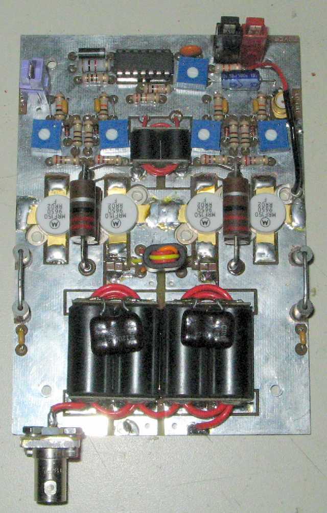
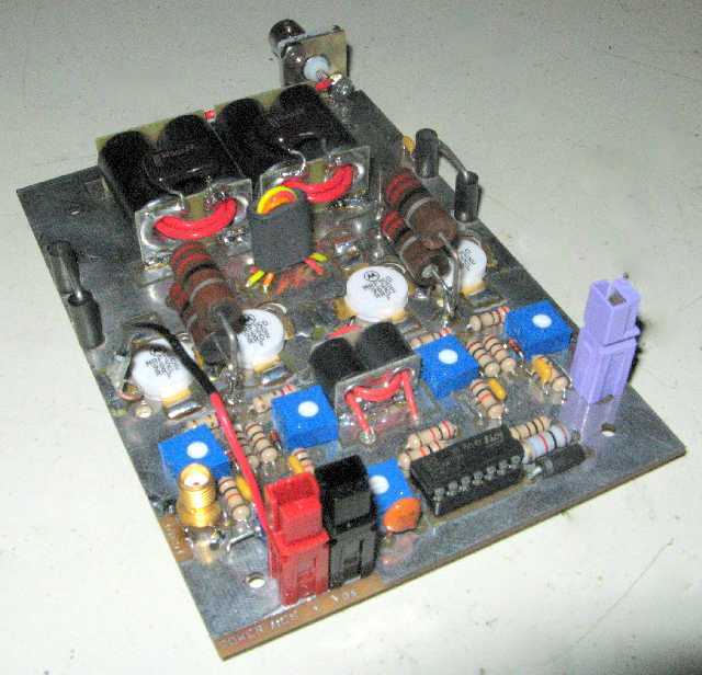
Each "Pallet" has 4 MRF-150 FETs, takes 6 watts drive, and produces 600 watts output
This amp will mount two pallets on each copper heat spreader. There will be a total of four pallets.
Click on photos to enlarge in separate window.
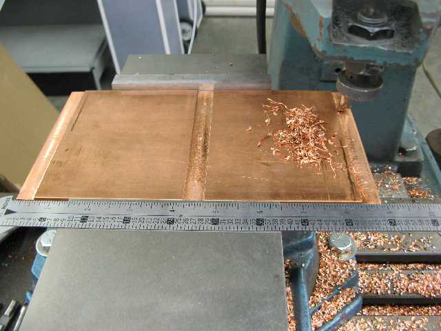
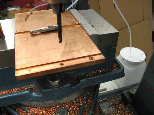
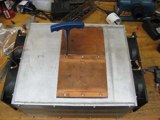
Milling shoulders on solid copper heat spreader Drilling / countersinking holes for bolts
Pallets are 3 5/8 X 5 1/8 - Copper heat spreader is 9 X 5 X 3/8 - note 1/2 inch channels along edges
and center to allow mounting to aluminum heat sink. There are 24 holes drilled and hand tapped
for 4-40 screws on each copper spreader to hold FETs and boards.
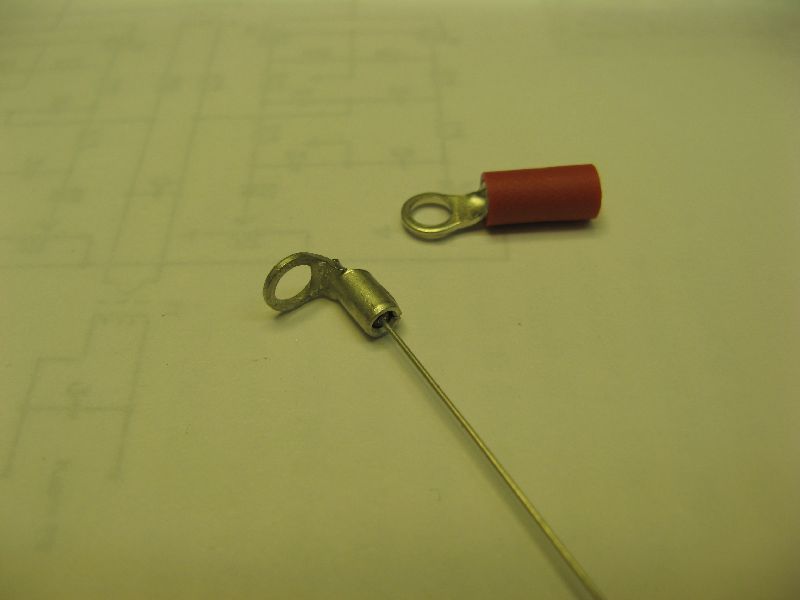
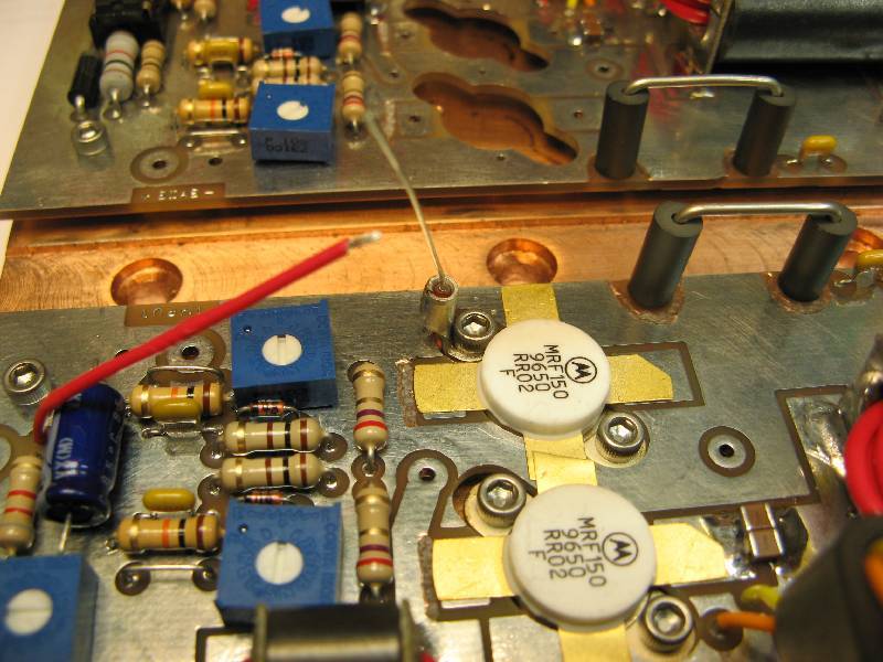
Close-up of thermistors, crimped & soldered Thermistor mounted to FET.
inside ring terminals Red wire connects to lead for BIAS tracking
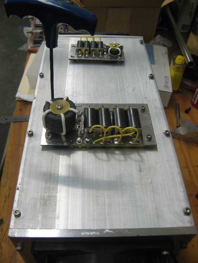
Four FETs in place, ready to be soldered to board. Closer view - holes in channels are counter-sunk,
FETs must be mounted to heat spreader first, then to allow for 10-32 socket head cap screws to mount
soldered, to prevent damage to FETs copper heat spreader to aluminum heat sink
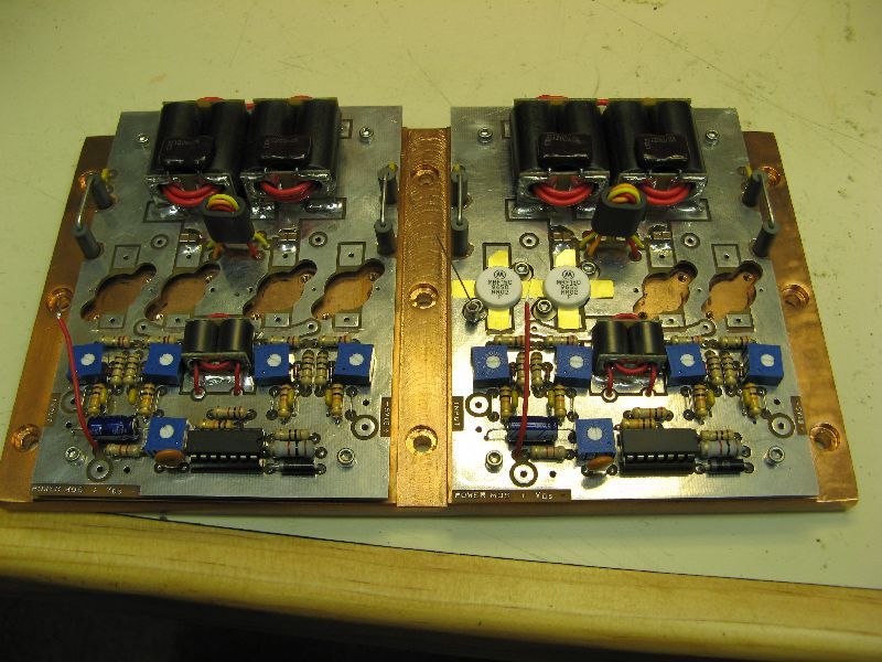
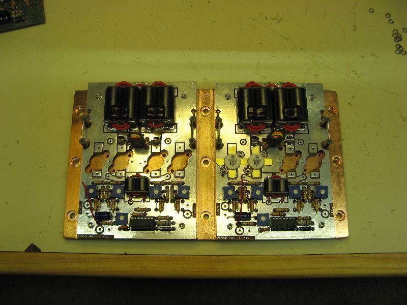
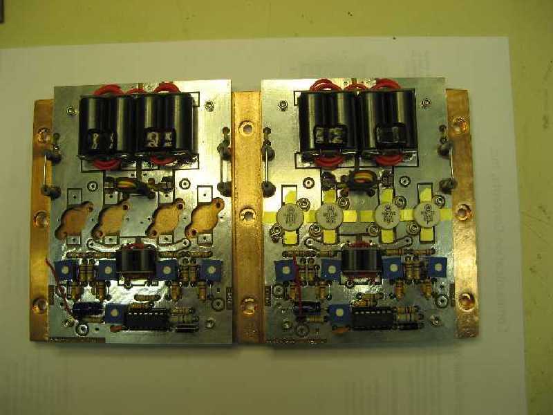
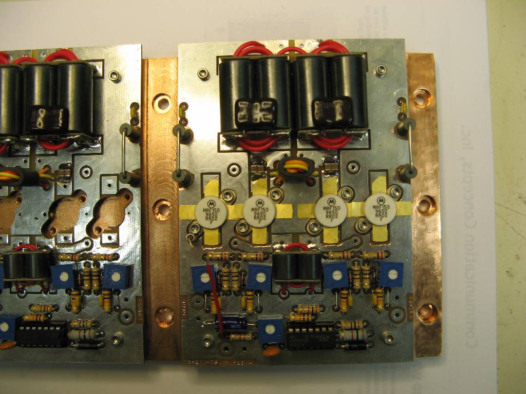
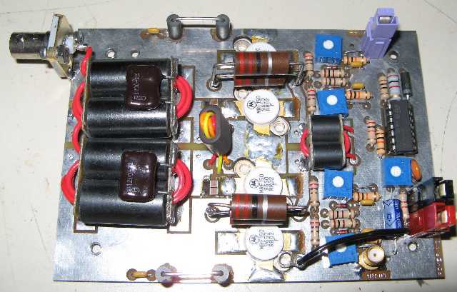
Views of Finished RF Pallets
To simplify changing boards, all inputs/outputs now have connectors
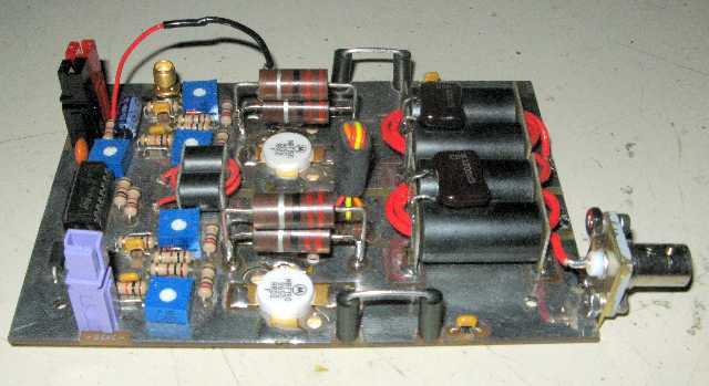
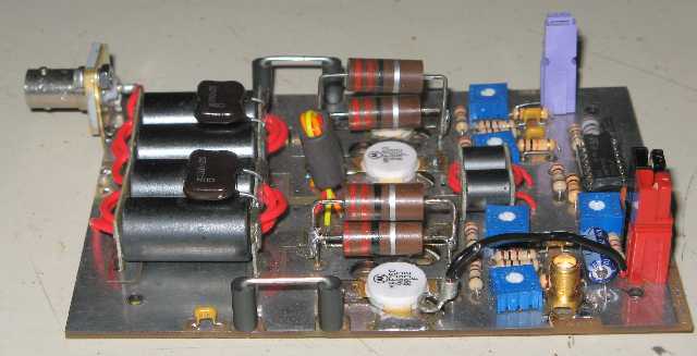
BNC connector added for RF output SMA connector added for RF input
BNC mount fabricated from Brass sheet PowerPole® connectors for DC (black & red) and bias (purple)
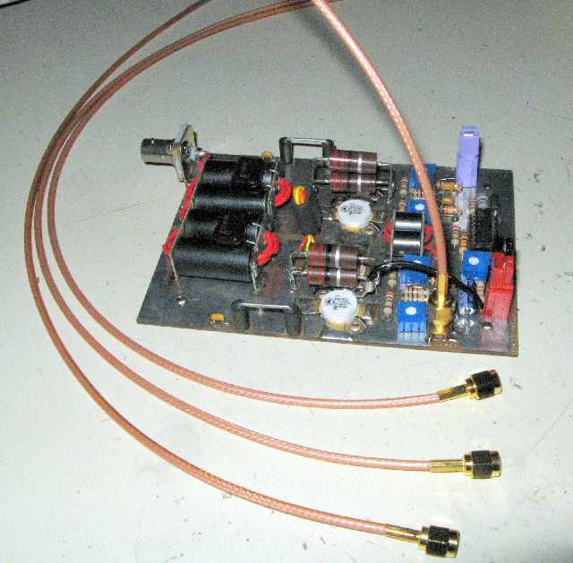
RG-316 cables, RF from splitter to pallet input
cut to +/- 1/32inch
New Views of RF deck / heat sink
Deck is 10.5 wide X 6 tall X 12 long. Base of sink is 3/8 thick aluminum
Sides and ends are 3/16 thick aluminum
Weighs 29 lb before any parts or copper added
4 - 120mm, 12V fans will provide cooling
All bolts/fasteners used in project are stainless steel
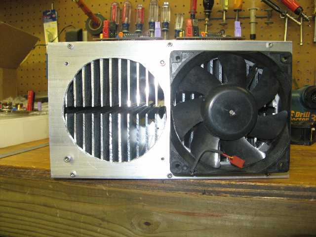
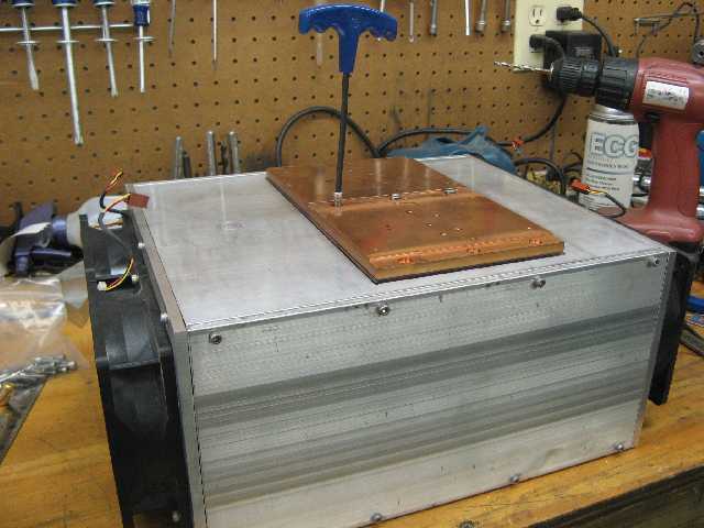
View from end of heat sink assy, one fan removed Mounting copper heat spreader to heat sink
Nine #10-32 screws will insure a snug fit Mounting the 4 way splitter and combiner to heat sink
and good heat transfer
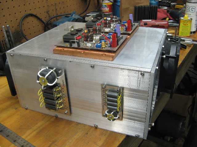
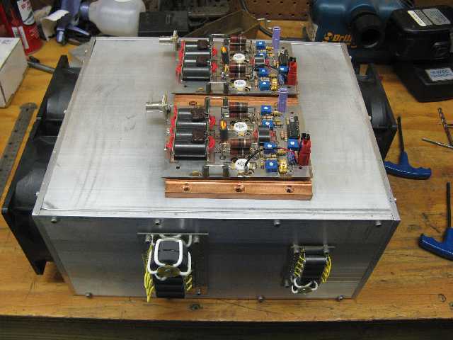
One side complete, once standoffs are added, Need to add balancing resistors for combiner / splitter
2 additional pallets will be mounted to other side and Selco's for temp sense to run fans
NEXT STEPS
A home brew Icom® band decoder
will be built and incorporated. (DONE, 7/29/09) A front panel,
7 position switch will allow manual or auto
selection of filters. LED's will give visual indication
of filter (band)
selected.
A stepped speed control for fans and the
band-pass filter boards are next items to work on.
On advice from K5RUS, went
with a thermistor based controller, providing totally variable
(quieter) speed
control, with a single Selco®
override for full speed if necessary.
(DONE,
8/11/09) (re-built w/ heavier duty parts for better long term reliability,
8/22/09)
I've decided to incorporate multi color LED
bar graphs to monitor forward and reflected power,
similar to what you see on
Alpha® amps. LED display
will be about 4 inches long, large enough
to actually see.
Several LM3914 IC's along with necessary LED's
were acquired to build the 20 led
(green / red) forward power bar graph, and the
10 led (green / yellow / red) reflected power bar graph.
Designing and building opto-coupler based
keying circuit. Sensor for "overtemp" will disable
keying and Bias,
and turn on front panel warning led. (parts acquired, 8/24/09)
Just after the last step was completed, a tree took down my main tower and 6 antenna. Even the best amp in the world won't help with no antenna, so since that time, I have focused on building tower(s) and stacked mono-band yagi's. Once all the outside hardware is in place, I hope to return to the amp project.